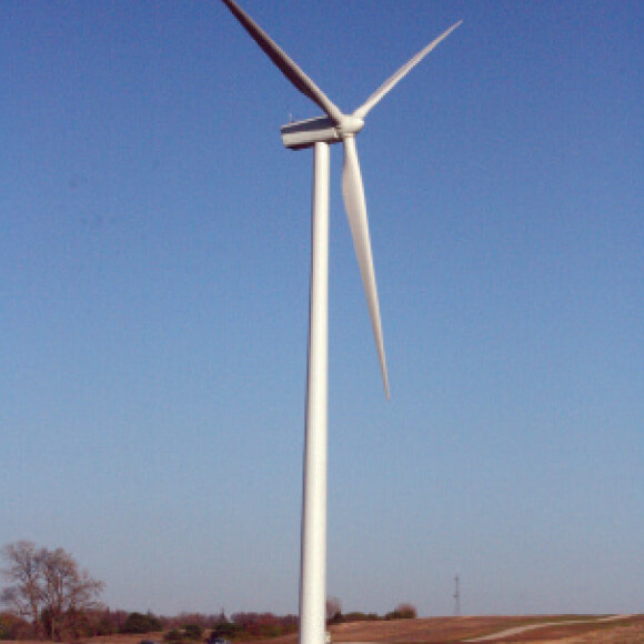
Winnebago 1 Windfarm
Using the Geopier GP3® system led to an optional foundation design where construction cost was minimized
- Developer: Iberdrola Renewable Energies, USA
- General Contractor: Iberdrola Inc.
- Geotechnical Engineer: Terracon
- Structural Engineer: EAPC
Construction of ten wind turbine towers. The towers are on octagonal footings with a width of 45 to 60 feet. Maximum design pressures were on the order of 4,165 psf and 2,180 psf for extreme and normal loading conditions. The sustained dead load pressure is 1,500 psf.
The soil profile generally consisted of medium stiff to stiff silty clay or lean clay loess or weathered glacial till materials to depths of about 13 to 18 feet over stiff to very stiff sandy lean clay glacial till.
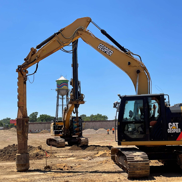
One of the interesting details of this project was the desire of the Project Developer to maximize the feasibility of the foundation cost by reviewing Rammed Aggregate Pier® (RAP) solutions for various bearing pressures. By increasing the bearing pressure with an appropriate RAP reinforcement solution the overall cost of the concrete, steel, excavation, etc. was reduced. Ultimately, it was determined that an RAP soil reinforcement solution creating a bearing pressure of up to 4,500 psf was the most economical for this project. RAP elements were installed in a configuration to satisfy this criteria extending to depths ranging from 7 to 15 feet below the foundation pad.
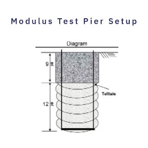
The test RAP element was installed near the planned wind turbine mat foundation on site. The test pier had a shaft length of 12 feet, and the top-of-pier elevation was set 9 feet below the working grade. Two telltales were set at the bottom of the reinforcing element, to monitor deflections at the base during the modulus test. A concrete cap was cast over the reinforcing element, and then a reaction frame was erected over the test element, with helical screw piles providing the uplift resistance.
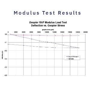
Modulus test results showed less than ¼-inch of top-of-Geopier deflection
The results of the test exceeded the design Geopier stiffness modulus of 175 pci at 100 percent of the design stress, with less than ¼-inch of top-of-Geopier deflection. The bottom telltales showed negligible deflection at 100 percent of the design stress, indicating that little if any stress was transferred to the bottom of the element.